| Templot Companion | search | remove search highlighting | if the A-Z Index tab is missing click here |
A. adjusting individual check and wing rail ends B. basic check and wing rail terms and dimensions C. clearance from nearby rails
A. Check Rail and Wing Rail End Adjustments:
These functions modify the basic settings for individual check rail and wing rail ends. This is intended for situations in complex formations comprised of partial templates.
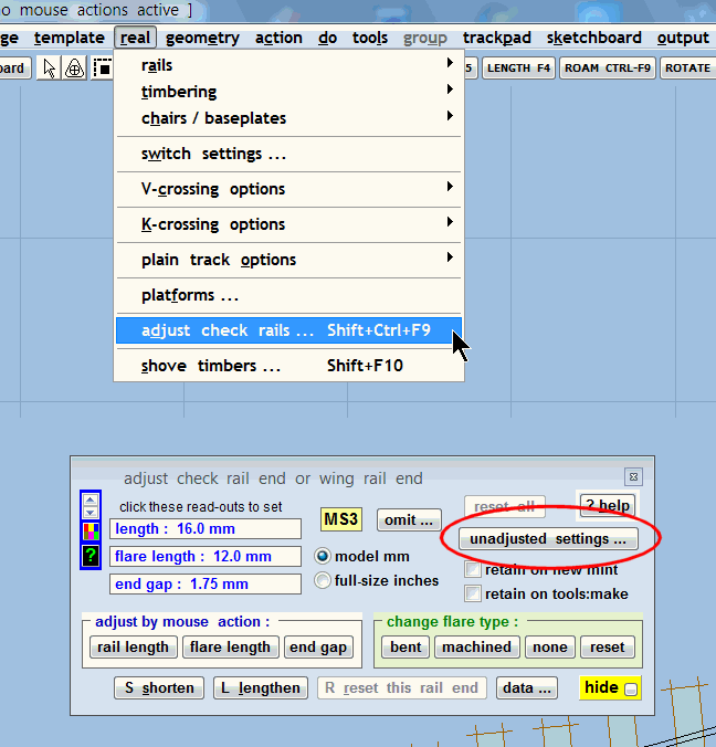
1. click the real > adjust check rails... menu item, or shortcuts SHIFT+CTRL-F9 or the FULL-STOP (.) (period) key. This dialog appears:

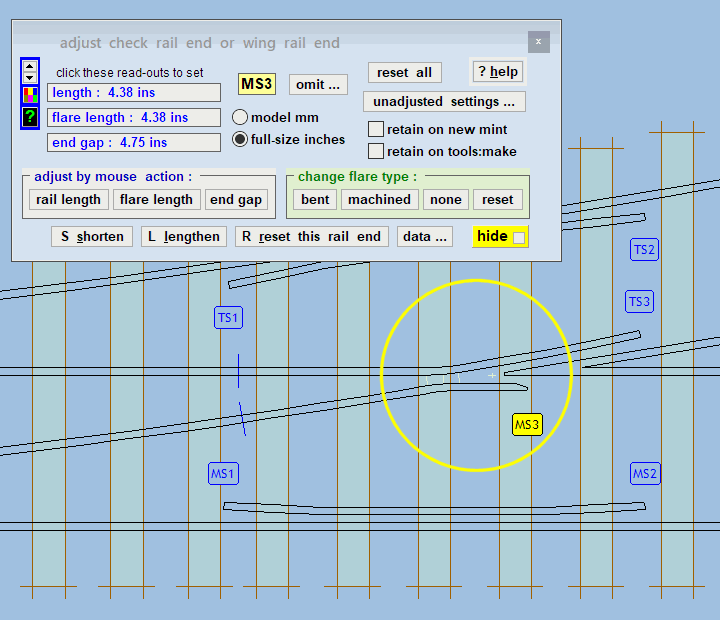
2. labels will appear on each rail end. Click the label (not the rail) to select the rail which you want to adjust. Each end of a check rail is adjusted separately.
MS1 MS2 MS3 TS1 TS2 TS3 MS4 DS4 |
3. use the buttons on the dialog to select the required mouse actions, etc., for the selected rail.
![]() In order to reduce a rail length to a very short dimension, it is necessary to first shorten the flare length. The rail length cannot be shorter than the flare length:
In order to reduce a rail length to a very short dimension, it is necessary to first shorten the flare length. The rail length cannot be shorter than the flare length:
If the retain on new mint box is ticked, any adjustments will be preserved when creating a new mint template. (Using the template > new template (quick set)... menu item, or the NEW tool-button.)
If the retain on tools: make box is ticked, any adjustments will be preserved when creating a new template using the tools > make --- menu items. This is the same setting as the tools > make tools: options > retain adjusted check rails menu option.
|
check rail flare types: The dialog has four flare choices: bent, machined, none, and reset. bent The flare is formed by bending the end of the rail. Normal for bullhead rail (BH). machined The rail is straight with a flare angle machined into the rail head. Nowadays most heavy flat-bottom rail (FB) in the UK uses machined flare angles on straight check and wing rails. This is mainly to allow for different lengths of flare angle (according to line speed) without the need for special baseplates. Lighter FB rail, such as that used on industrial, narrow-gauge, and light railways normally has bent flare angles because it is much less expensive to make than a machined flare, and easier to repair on site. none No flare on this rail end. This is mainly for use in building complex formations from partial templates. reset Returns this rail end to the basic setting. |
These functions are primarily for use on partial templates in complex formations. The basic prototype settings remain as set at real > V-crossing options > customize V-crossing > wing and check rails... menu item, or can be accessed by clicking the unadjusted settings... button on the dialog. The above adjustments modify these basic settings for each rail end individually.
B. Wing and check rail basic terms and dimensions:
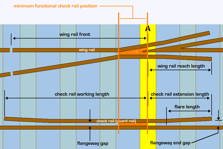
This diagram explains the wing rail and check rail (guard rail) terminology used in Templot. Everything is referenced from the centre of the "A" timber -- the one supporting the nose of the crossing vee:

The wing rails are the short lengths of running rail with bent extensions which lie alongside the nose of the crossing vee. The wing rail "reach" length is measured from the centre of the "A" timber (the timber bearing the nose of the vee) to the free end of the wing rail.
The check rails (guard rails) are the short lengths of rail fixed alongside the opposite running rail to prevent the wheels from taking the wrong path at the nose of the crossing. For dimensioning purposes the overall length of a check rail is divided into two component lengths, named "working length" and "extension length".
The check rail "working" length is measured from the position where it crosses the centre-line of the "A" timber, to the near end of the check rail (the end which is nearer to the switch) (point blades).
The check rail "extension" length is the remaining length from the "A" timber to the far end of the check rail.
Each exposed end of a check rail or wing rail has an angled "flare" length on which wheel flanges can make contact and be brought smoothly under the control of the rail. In bullhead track the flared part is normally arranged by simply bending the end of the rail, for which special handed chairs are provided. Sometimes in cramped designs the flare angle is machined into the head of a straight rail.
The basic prototype-based settings for the above are set at real > V-crossing options > customize V-crossing > wing and check rails... menu item, or by clicking the unadjusted settings... button on the dialog:
The functional length of a check rail (i.e. the middle section between the flared ends) must at least cover the break in the opposite rail, so that wheel flanges are prevented from striking the nose of the crossing. So for a V-crossing that means from the knuckle bend in the wing rail approximately to the centre of the "A" timber:
In practice of course it would be very unusual to have such a short minimal check rail. It would need a severe speed restriction and is only likely to be found in yards and sidings.
Note that for model gauges with overscale flangeway gaps, the knuckle is further from the nose than on the prototype and hence the minimum check rail will be longer to ensure proper running.
The check rail is much more important for traffic running in a facing direction, so the working length of a check rail is normally much longer than the extension length. If a very short check rail is necessary, the working length should have priority in the design.
The length of the flared end on a check rail is governed by the line speed. High speeds require a longer and easier flare to avoid shock as the wheel makes contact. In yards and sidings the bent flare can be quite short if necessary, maybe just a few inches beyond the last plain check chair.
For running line bullhead track with bent flares, the check flare length is largely determined by the available left and right special angled check-end chairs. This is one reason why modern flat-bottom track uses machined flares instead of bent, so that the flare length and angle can be set to match the line speed.
Templot uses 2 sizes of wing rail reach length, 3 sizes of check rail working length and 2 sizes of check rail extension length, according to the V-crossing angle. These sizes are pre-set in increasing lengths, but can be set to be all the same, or to any desired lengths.
Here is a summary of the way these sizes are used according to the current V-crossing angle:
V-crossing check rail check rail wing rail
angle: working length: extension length: reach length:
under 1:6 size 1 size 1 size 1
1:6 to 1:10 size 2 size 1 size 1
over 1:10 to 1:12 size 2 size 2 size 2
over 1:12 size 3 size 2 size 2
When customizing the dimensions at real > V-crossing options > customize V-crossing > wing and check rails... menu item (or by clicking the unadjusted settings... button on the adjustments dialog) be sure that you are changing the settings for the appropriate size according to the current V-crossing angle. Otherwise your changes will have no effect.
In the majority of cases, the check rail extension length is the same dimension as the wing rail reach length, so that the far end of the check rail is aligned with the end of the wing rail, but this can be changed as necessary by entering the appropriate dimensions.
Be aware that because the check rails are linked to the "A" timber, the position of the check rails will change when changing the style of timbering (equalized, square-on, or angled-on). But their position is not affected by any timber shoving which is applied to the "A" timber.
|
Continuous check rails It is not possible for a plain track template to have check rails. However, a length of plain track with a continuous check rail on one side (for use on sharp curves), or both sides (for use in roadways and level crossings), can be created by modifying a turnout template. First add some approach track ( F3 mouse action) of suitable length. Then increase the MS1 or TS1 check rail working length sufficiently to extend the check rail(s) back into the approach track. Then put the fixing peg at the toe joint ( CTRL-1 ) and click do > snap to peg menu item. To create a full length of continuous check rail with flared ends at both ends, peg two such templates together at their CTRL-1 positions. Or tick the retain on tools: make box and then click the tools > make mirror on peg menu item. To swap a single check rail to the opposite side, click the template > invert handing menu item (or CTRL-X ). Remember that despite appearances these are turnout templates, so to adjust their length use the F3 approach length mouse action (not F4 ). More information: http://85a.co.uk/forum/view_topic.php?id=2580&forum_id=6 |
C. Clearance from nearby running rails:
For required clearance between the exposed ends of wing rails and nearby running rails, for example in a tandem turnout, see:
http://85a.co.uk/forum/view_topic.php?id=1465&forum_id=1
link to this page: https://85a.uk/templot/companion/check_and_wing_rails.php