| Templot Companion | search | remove search highlighting | if the A-Z Index tab is missing click here |
a page about using transition curves in Templot
Transition curves are used often in Templot -- rather more than on the prototype.
On the prototype transition curves are normally found only on fast running lines, where they are invariably canted, i.e. given superelevation where the outer rail is higher than the inner rail. The transition curve provides a length in which the rails can rise and fall from level track. It would be unusual to find pointwork in a prototype transition curve. It would be very unusual to find a transition curve in a goods yard.
On a model we are often working in limited space with very sharp curves in prototype terms. Transition curves, even on the flat, provide a good way to disguise the severity of such curves, and provide a means to create flowing track in cramped spaces. Running a transition curve through some pointwork and along a siding helps to create the spacious effect of the prototype, in a limited model space.
For such needs Templot can create a transition curve between two existing curves. This is the usual way to create a link between two existing templates. For more about that process see link between existing templates.

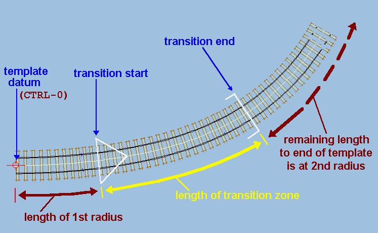
In a transition curve, the curving radius is progressively changed from the 1st or initial radius to the 2nd or final radius within the length of the transition zone.
Any track preceding the start point of the transition zone will be curved at the 1st radius. Any track beyond the end point of the transition zone will be curved at the 2nd radius.
The 2nd radius can be larger or smaller than the 1st radius, and the transition zone length can be set to zero if an instant change of radius is desired.
It is possible for one of the radii to be straight, but not both. In which case such a transition curve is often called an easement to or from straight.

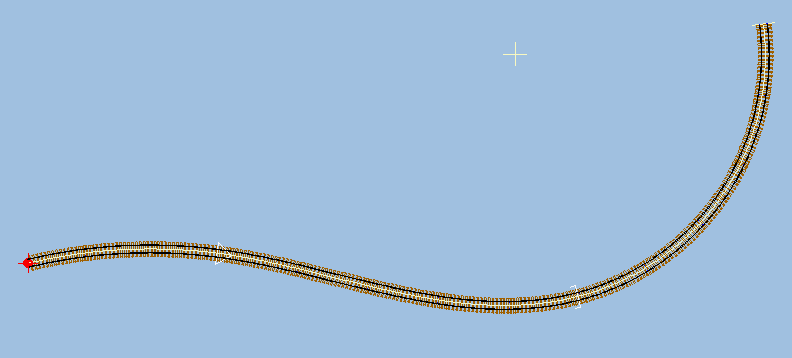
If the 1st radius is positive and the 2nd radius negative, or vice versa, an S-curve effect is achieved, as in the diagram above. For further explanation of the meaning of a negative radius see constant-radius curves.
A transition curve is selected for the control template by clicking the geometry > transition curve > menu items.
Before selecting the easement settings you will normally want to ensure that the fixing peg is at the curved end of the template, so that the newly modified template remains in alignment with the previous curve.
For easements the transition zone length is set to 2 chains (132ft) (scale), unless this is more than 95% of the current length of the control template, and the length of the straight section is set to zero. You will probably want to change these settings afterwards to suit your requirements for each situation.
•Selecting as previous settings sets a new transition curve with the same radii and length settings that were last used for a transition curve. If the control template already contains a transition curve, this option is disabled.
•Selecting new transition settings... brings up the Templot data entry form on which you can enter your required radii and length settings for the new transition curve.
The start and end points for the transition zone section of the curve are indicated by special marks across the track. The transition start mark is a large arrow-head symbol pointing into the transition zone, and the transition end mark resembles a set of "goalposts" (see the diagram above).
To move the whole transition zone along the track, select the move transition start mouse action (SHIFT+CTRL+F3 or just press the [ (left square bracket) key).
To lengthen or shorten the transition zone, select the adjust transition length mouse action (SHIFT+CTRL+F4 or just press the ] (right square bracket) key).
The transition radii are adjusted using the same adjust curving radius (F6) mouse action as for a constant-radius curve. To toggle between adjusting the 1st or 2nd radius, click the triangle symbol on the mouse action panel. Or select either of the action > transition radius options > menu items (SHIFT+CTRL+F1 or SHIFT+CTRL+F2), or press the - (minus) or = (equals) keys for 1st or 2nd radius respectively. You can do this while the mouse action is in force.
![]() These1st or 2nd radius selections also apply to other mouse actions such as the CTRL+F5 orbit function. The BACKSPACE key continues to work normally to repeat a previous mouse action.
These1st or 2nd radius selections also apply to other mouse actions such as the CTRL+F5 orbit function. The BACKSPACE key continues to work normally to repeat a previous mouse action.
To enter the radius and length settings directly, select the geometry > radius and curving... menu item while a transition curve is in force, or click the figures showing on the lower line of text on the mouse action panel.
|
When using the move transition start and adjust transition length mouse actions, there are two options for the way the transition curve is calculated, at the action > transition zone options > menu items. The radii fixed (normal) option maintains the 1st and 2nd radii constant, and adjusts the transition alignment between them accordingly. The transition fixed (roll-out) option maintains a constant alignment in the transition zone, and adjusts the 1st or 2nd radius accordingly. This setting reverts to the radii fixed (normal) option whenever a new transition curve is set up. |
As for the other mouse actions, the way in which the template responds to transition curve adjustments is determined by the position of the fixing peg within it. Normally, before making an adjustment, the fixing peg should be moved to a position where you want the template alignment to remain unchanged.
A frequent need is to slide a template along a transition curve alignment without disturbing the alignment. This is done using the snake (CTRL+F6) mouse action. Compare the results with the otherwise similar slide (SHIFT+F9) mouse action.
In addition, a transition curve can be combined with a slew to give a virtually unlimited range of alignments. Click for more information about slewing, or see the notes at the geometry > slew (nudge) > ? slew - help menu item.
When changing from a transition curve to a constant-radius template, geometry > constant radius menu item, the new constant radius will be the radius at the current position of the fixing peg within the transition template.
For more information about the transition mathematics, see the notes for the program > expert > transition maths > custom terms... menu item on the program panel ( program > show main program panel menu item).
This page will be updated with more information and diagrams soon.
link to this page: https://85a.uk/templot/companion/transition_curves.php