
Thank you for ordering our 0 Gauge Hunslet locomotive kit. We hope that the kit meets with your approval and that our service has been satisfactory - if not please let us know. If you need further details about the model or any other information we will always be happy to help.
If this will be your first 0 Gauge locomotive, we are sure that you have made a wise choice and that your new Hunslet will soon be running on your railway.
If you are an "old hand" in 7mm, we hope that you enjoy building the Hunslet; it makes a pleasant change from the demands of more complex metal kits.
Happy Shunting!
This product is not a toy and is not suitable for young
children. It contains sharp edges and toxic materials. Track, rolling stock
and power-supply are not included.
This kit contains all the parts needed to build a finely-detailed working
scale model locomotive, but does not include glue, paint, transfers, additional
weights.
Some of the smaller components in this kit are delicate mouldings. Please
unpack and handle them carefully. Since these notes were written we may have
made some packing changes. If parts are supplied loose please ignore instructions
to remove them from the moulding runners.
DO NOT OIL the chassis unit - use ONLY the special grease supplied - read
the notes about lubrication in section A.
Please include these notes with the model if you sell it.
We have tried to produce a model which is enjoyable and trouble-free to build. Please let us know if anything is unclear - we welcome your comments and suggestions.
# refers to the component part numbers
shown on the exploded illustration.
![]() highlights a caution or
warning.
highlights a caution or
warning.
![]() indicates possible modifications.
indicates possible modifications.
![]() refers to an explanatory footnote.
refers to an explanatory footnote.
![]() highlights other points of
interest.
highlights other points of
interest.
A. Information For Owners - running, maintenance
and storage of the finished model. This page should be kept in the box with
the model and included if you sell it.
B. Adhesives, Paints, Tools - some notes on materials
and methods.
C. Assembly Sequence - the "words and music" on
which bit goes where.
D. Parts List and Exploded Diagram.
E. Additional Information and Update - odd points
omitted from the notes and/or arising from customer feedback. If some time
has elapsed since you obtained the kit, please send for the latest version
of section E, or see our internet web site at www.85a.co.uk
The web site also includes some pictures of finished models, and contributions from other modellers about our Hunslet kit.
This model is for use only on 2-rail systems using a nominal 12 volts DC
power supply.
Unless otherwise stated this model is intended to be run on O Gauge (32.0
mm gauge) track with pointwork clearances set to the Gauge O Guild fine-standard
dimensions. It may be possible to run without problems on other tracks.
At shunting speeds in yards and sidings, the model will negotiate curves
down to 20 in. (500 mm) radius. In practice the minimum working radius is
usually determined by other factors such as buffer-locking between wagons.
For continuous running, curves should not be less than about 30 in. (750
mm) radius to avoid undue wear in the working components.
The working chassis unit and all the body parts can be supplied separately
if required, but we are unable to supply the wheels or axles separately.
If any of the body parts are damaged during assembly you may return them
for a free replacement, quoting the model serial number shown on the box.
The saddle-tank parts are supplied pre-drilled for handrails. If you would
have preferred to receive them undrilled, please return them for a swap.
In the unlikely event of the chassis unit becoming faulty within 12 months from
the date of purchase it will of course be repaired or replaced free of charge.
If the chassis unit has been built into a finished model, we can only accept
it for repair on the basis that the value of the model does not exceed the
current price of an unassembled kit. Please contact
us first before sending, so that we can advise on packing, etc.
Please read through these notes before building the chassis unit
# 8 into your model. Remove any packing
and other parts packed with the chassis unit before attempting to run it.
![]() Do not attempt to turn the wheels
by hand. To adjust the position of the wheels, rotate the upper end of the
motor shaft.
Do not attempt to turn the wheels
by hand. To adjust the position of the wheels, rotate the upper end of the
motor shaft.
Test the chassis unit on the track. Adhesion and electrical pickup will be
improved when the unit is carrying the full weight of the finished model.
This can be simulated for testing purposes by adding a few coins or
washers.
The motor has been carefully matched to its mounting for optimum performance.
This results sometimes in a motor which is rotated slightly from a square-on
position in the chassis. This is not a fault - the screws sealed with yellow
paint should not be disturbed.
The chassis unit has been lubricated, tested and inspected before leaving
our workshop and should run for many hours before needing any servicing.
![]() The motor is a maintenance-free
unit sealed for life and should never need any attention.
The motor is a maintenance-free
unit sealed for life and should never need any attention.
![]() Other parts may need a little
lubrication from time to time. USE ONLY THE SPECIAL GREASE SUPPLIED for this
purpose, as other oils or grease may attack or soften the moulded
components.
Other parts may need a little
lubrication from time to time. USE ONLY THE SPECIAL GREASE SUPPLIED for this
purpose, as other oils or grease may attack or soften the moulded
components.
Apply the grease very sparingly on a needle or stiff wire to :
![]() Axles adjacent to the frame bushes
while the motor is running. Power can be applied from an electric wheel-cleaning
brush or by attaching small clips to the central pickup terminals. Using
a lint-free cloth, wipe off any surplus grease, leaving just a thin film
on the axles where they run against the pickup strips.
Axles adjacent to the frame bushes
while the motor is running. Power can be applied from an electric wheel-cleaning
brush or by attaching small clips to the central pickup terminals. Using
a lint-free cloth, wipe off any surplus grease, leaving just a thin film
on the axles where they run against the pickup strips.
![]() Crankpins where they rotate in
the back of each wheel, and between the coupling rods and the face of each
wheel.
Crankpins where they rotate in
the back of each wheel, and between the coupling rods and the face of each
wheel.
![]() Gears. Just a little, as excess
grease on the gears may get thrown off onto the track.
Gears. Just a little, as excess
grease on the gears may get thrown off onto the track.
![]() Do not use any sort of oil or
grease to lubricate the buffers. If the working action becomes "sticky",
dust a little talc powder onto the buffer shanks.
Do not use any sort of oil or
grease to lubricate the buffers. If the working action becomes "sticky",
dust a little talc powder onto the buffer shanks.
If the model is run in dusty conditions, the wheel rims may become dirty,
leading to problems with electrical pickup and erratic running.
To clean the wheels, run the rim against a cotton- bud lightly dampened with
"3-IN-ONE" or similar household lubricating oil until all the soiling has
been loosened, and finish with a dry cotton-bud. Wipe off any oil which strays
onto the wheel centres or other parts.
![]() DO NOT use this oil to lubricate
the working parts - use only the special grease supplied.
DO NOT use this oil to lubricate
the working parts - use only the special grease supplied.
If there is an excessive build-up of dirt on the wheels it should first be
scraped away with a suitable tool. (A length of plastic moulding runner filed
to a chisel end will avoid damaging the rims.)
![]() The use of abrasive cleaners
such as a fibreglass burnishing pencil, emery paper or abrasive rubber blocks
is not recommended - the particles shed may become embedded in the working
components, leading to permanent damage.
The use of abrasive cleaners
such as a fibreglass burnishing pencil, emery paper or abrasive rubber blocks
is not recommended - the particles shed may become embedded in the working
components, leading to permanent damage.
![]() Do not use any form of degreasing
agent (for example white spirit) or solvent to clean the wheels as this will
promote rapid rusting.
Do not use any form of degreasing
agent (for example white spirit) or solvent to clean the wheels as this will
promote rapid rusting.
Variable-pulse-width controller systems are not necessary and may cause
overheating of the motor. The drive is geared 40:1 to give smooth responsive
control with conventional variable- voltage controllers. If the model has
not been over-weighted, the maximum current consumption (when slipping) is
less than 350 mA, so special high-power "O Gauge" controllers are not
needed.
In the very unlikely event of a failed motor, it is replaceable from below
the chassis (after removal of the wheelsets and pickups); it is not necessary
to dismantle any part of the body. We can do this work for you (see Faults
and Repairs above), or we can supply the necessary replacement parts and
guidance notes.
![]() The Mashima motors used are very
reliable. Even so, each one is carefully tested before use. (At the time
of writing (May 1997), we have been producing these models for over 4 years,
and so far remain unaware of a single case of motor failure.)
The Mashima motors used are very
reliable. Even so, each one is carefully tested before use. (At the time
of writing (May 1997), we have been producing these models for over 4 years,
and so far remain unaware of a single case of motor failure.)
Gear-mesh adjustment is possible without removal of the motor or wheels.
This is very unlikely to be necessary - do not disturb the adjusting
screws.
This model can be used out of doors on fine days but cannot be expected to
withstand extreme climatic conditions.
![]() Do not leave the model standing
for long periods in hot sun, especially if behind glass.
Do not leave the model standing
for long periods in hot sun, especially if behind glass.
As with all models having steel wheel rims, these may rust if the model is
stored during the winter months in unheated outbuildings. Some protection
is possible by oiling the rims (see Wheel Cleaning above), but wherever possible
the model should be stored indoors when not in use.
![]() Do not store the model for long
periods with the buffers fully compressed, for example by storing the box
on end with the model loose inside. The working action of the buffers may
be harmed.
Do not store the model for long
periods with the buffers fully compressed, for example by storing the box
on end with the model loose inside. The working action of the buffers may
be harmed.
A detailed history and drawing of the Hunslet 15" engines is in the September
1986 issue of "Model Railway Constructor". Your local library or model railway
club should be able to show you a copy.
The preview edition (November 1995) of "Rail Model Digest" contains a review
of this kit and some ideas for further detailing. Available from PO Box 2,
Chagford, Devon, TQ13 8TZ. £5.95
The majority of industrial locomotives were finished in a plain black livery,
usually with red buffer beams and often with red coupling rods. Sometimes
the reversing rod was also red.
But some industrial owners adopted very colourful painting schemes. The Ian
Allan colour album "Industrial Steam" is a rich source of ideas. ( ISBN
0-7110-2230-5, 1994, £10.99 from most bookshops).
There are two Hunslet 15" engines in this book. On page 43 "Airedale" is
finished in fully lined LMS red. This was the first of the class and differs
slightly from later engines. Note the curved corners on the buffer beams,
larger cap on the front sandboxes, and beading around the cab sidesheets.
On page 46 "Jubilee" has acquired an additional set of steps, and is painted
apple green with yellow lining. Page 25 shows a pair of Hunslet 16" engines,
which are very similar. These have green panels on black, with red lining.
![]() "Just glue and paint needed to
complete" it says on the box. But there is a wide range of different adhesives
and paints to choose from in your local model shop, and it is possible to
spoil this model by using the wrong ones. So for newcomers to modelmaking
we have listed below our recommendations in some detail.
"Just glue and paint needed to
complete" it says on the box. But there is a wide range of different adhesives
and paints to choose from in your local model shop, and it is possible to
spoil this model by using the wrong ones. So for newcomers to modelmaking
we have listed below our recommendations in some detail.
For the main structure of the model we advise using a traditional polystyrene
cement, which is applied to the mating surfaces before uniting them. This
produces a stronger bond than a liquid solvent. We recommend "Humbrol Precision
Poly" cement which comes in a handy squeeze bottle with a fine metal applicator
tube and is much cleaner in use than tube cement.
For some of the smaller parts a liquid solvent such as "Humbrol Liquid Poly"
or "Slater's Mek-Pak" is more convenient, and here the method is different.
The parts are held firmly together dry while the solvent is applied along
the back of the joint using a fine brush.
![]() At the time of writing "Slater's
Mek-Pak" is our preferred solvent. It is less agressive than some other solvents
and is therefore more forgiving of excess application. But solvent compositions
may change due to Health and Safety regulations - use adequate ventilation
and no smoking with all of them.
At the time of writing "Slater's
Mek-Pak" is our preferred solvent. It is less agressive than some other solvents
and is therefore more forgiving of excess application. But solvent compositions
may change due to Health and Safety regulations - use adequate ventilation
and no smoking with all of them.
Some of the detail parts (whistle, smokebox door handles, and coupling hooks)
are moulded in an unbreakable material for which the above adhesives are
not suitable, and for these we recommend cyano gel adhesive - "Superglue
Gel". This is also used to fix the working buffer heads.
![]() Do not use ordinary thin
superglue.
Do not use ordinary thin
superglue.
A filler such as "Humbrol Model Filler" may be needed for the joint in the
saddle tank and in case of accidents. "Milliput" 2-part epoxy filler is suitable
for larger gaps and for fixing any additional weights. Also needed is a little
white pva wood glue ("Resin-W" or similar) to fix the coal supplied for the
bunker.
![]() Do not allow any excess cement
to stray onto the surface of the mouldings. If this does happen do not attempt
to wipe it off as this will make matters worse. Leave it for at least 24
hours to harden, after which time it can be filed or sanded off and the surface
reinstated if necessary with filler. Any severely damaged body parts can
be replaced free of charge.
Do not allow any excess cement
to stray onto the surface of the mouldings. If this does happen do not attempt
to wipe it off as this will make matters worse. Leave it for at least 24
hours to harden, after which time it can be filed or sanded off and the surface
reinstated if necessary with filler. Any severely damaged body parts can
be replaced free of charge.
It is worth giving some thought to the final painting and finishing of the
model before beginning to assemble it. For a complex livery you may want
to paint some of the parts first - the interior of the cab for example. Keep
paint away from the glueing surfaces - "Humbrol Maskol" is useful for this
purpose.
Before any painting the model should be cleaned by wiping over with a
plastic-safe cleaning fluid on a lint-free cloth to remove all grease and
finger marks. "Humbrol Enamel Thinners" is suitable for this. Ensure that
it is completely dry before over- painting. Avoid the use of ordinary white
spirit for cleaning purposes, it can cause a fine crazing of the plastic
surface which promotes subsequent solvent attack.
![]() Keep cleaning fluids away from
the wheel rims and axles to avoid rust problems.
Keep cleaning fluids away from
the wheel rims and axles to avoid rust problems.
Wipe the model very gently when cleaning, as furious rubbing will generate
a static charge on the plastic surface, attracting dust particles as fast
as you try to remove them. If dust and static do become a problem, they can
usually be blown away with an air-blast from an empty airbrush, bicycle pump
or similar. Clean air-duster aerosols are also available from electronics
suppliers. Dust-absorbing tack-cloths are another useful aid (from car body
shops).
![]() If available we prefer pure I.P.A.
(isopropanol) for cleaning. It is quick-drying and completely safe on plastic
materials, so it can be freely used for degreasing purposes. It can be obtained
from electronics suppliers.
If available we prefer pure I.P.A.
(isopropanol) for cleaning. It is quick-drying and completely safe on plastic
materials, so it can be freely used for degreasing purposes. It can be obtained
from electronics suppliers.
![]() The plastic materials used in
this model require great care in the choice of suitable paints :
The plastic materials used in
this model require great care in the choice of suitable paints :
We recommend traditional model paints such as "Humbrol Enamel", which are
safe on plastics, and can give excellent results if a good quality artist's
brush is used from a new tin which has been well-stirred. They can also be
airbrushed very successfully using the proper enamel thinners (and good
ventilation). Enamels may require a few days to harden fully, so keep the
model covered to protect it from dust.
The coupling rods are moulded in an unbreakable material and are a special
case. Enamel paints may not adhere to them well, so if painted (usually red)
rods are required, we suggest using a water-based acrylic model paint such
as "Tamiya" or "Humbrol Acrylic Colour". A satin red can be produced by trial
mixing of gloss and matt reds. Two coats will usually be needed. It is not
possible to remove the coupling rods from the wheels for painting, so it
will be advisable to mask around them with paper or masking tape. For this
reason it may be easier to paint the rods before assembling the body onto
the chassis unit.
![]() Caution : Some modellers prefer
to use aerosol cans of car spray paint, which are convenient and quick. But
despite the claim on some modern cans that these paints are safe on plastic
materials, all of them, including primers and acrylics, contain solvents
which will attack or damage the material used in this model, so great care
is essential.
Caution : Some modellers prefer
to use aerosol cans of car spray paint, which are convenient and quick. But
despite the claim on some modern cans that these paints are safe on plastic
materials, all of them, including primers and acrylics, contain solvents
which will attack or damage the material used in this model, so great care
is essential.
If you intend using car aerosols, and have not used them on plastic kits
before, we strongly recommend that you first try them on a simple inexpensive
kit. A crazed or fuzzy finish may be acceptable on an ordinary open wagon
in everyday condition, but is not usually wanted on a polished locomotive.
The car sprays available from Halfords motorist shops seem to be less damaging
than some other types.
Aerosol enamels are also available from model shops and d.i.y. stores. Some
of these are safe on plastics, some are not. They usually take longer to
dry than car sprays.
If you do decide to risk aerosols, observe the warnings on the cans, and
make sure that you first test the actual cans you intend using on the back
of one of the mouldings. We cannot accept responsibility for models damaged
by aerosol paints - if in any doubt use Humbrol!
Only the usual small modelling tools are needed to build this model. The
basic essentials are :
![]() Sharp craft knife
Sharp craft knife
![]() Fine paint brush
Fine paint brush
![]() Tweezers
Tweezers
![]() A few small drill bits
A few small drill bits
![]() Flat needle file
Flat needle file
![]() Round pointed needle file
Round pointed needle file
A hand-held pin vice for the drill bits gives better control than hand or
power drills. Small flush-cutting electronics snips are useful for cutting
parts from the moulding runners and general trimming.
Masking tape, "Blu-Tack" and a selection of rubber bands will all prove handy.
Some fine abrasive sanding paper is supplied in the kit.
![]() The materials and tools mentioned
above should all be available from a good model shop, or from the sources
indicated. Most good toyshops also stock some of the Humbrol items. For
electronics items, the MAPLIN-MPS catalogue (from branches of W H SMITH)
lists these and many other useful modelling tools and supplies.
The materials and tools mentioned
above should all be available from a good model shop, or from the sources
indicated. Most good toyshops also stock some of the Humbrol items. For
electronics items, the MAPLIN-MPS catalogue (from branches of W H SMITH)
lists these and many other useful modelling tools and supplies.
![]() If you are new to modelling and
need further advice or a helping hand, your local model railway club should
be able to help, and most model railway exhibitions include model building
demonstrations.
If you are new to modelling and
need further advice or a helping hand, your local model railway club should
be able to help, and most model railway exhibitions include model building
demonstrations.
![]() The Gauge O Guild has many active
local area groups where newcomers to O gauge will be made very welcome. The
Guild offers many services and assistance to members. We will be pleased
to forward membership enquiries.
The Gauge O Guild has many active
local area groups where newcomers to O gauge will be made very welcome. The
Guild offers many services and assistance to members. We will be pleased
to forward membership enquiries.
revised 4-97 (c) 85A MODELS
Please read all through these notes and clarify any points of doubt before
proceeding. Some parts are handed right and left or could be fitted the wrong
way round. The # symbol refers to
the part numbers shown on the exploded illustration.
![]() Clear a suitable working space
before starting. The plastic mouldings are easily damaged if jumbled together
on the bench with sharp tools.
Clear a suitable working space
before starting. The plastic mouldings are easily damaged if jumbled together
on the bench with sharp tools.
First examine and identify each of the mouldings. They are produced in precision
tools and should be clean and generally flash-free with sharp square edges.
Occasional surface streaks are normal and will disappear under the paint
finish.
A little final fettling with a sharp knife or a fine file may be needed to
achieve the best fit. Always try parts together dry before applying any cement.
Time spent ensuring accurate close-fitting joints will be well repaid.
The assembly sequence in outline is :
| 1: | Fit the tank filler cap, assemble the upper and lower tank parts and
leave to set.
|
| 2: | Fit cab detail, assemble the upper and lower cab parts and leave to set. |
| 3: | Fit the door hinge bar to the smokebox. |
| 4: | Assemble the brake hangers to the brake rigging. Detach from the chassis when set. |
| 5: | When set hard, fettle the tank joins. |
| 6: | Fit the tank handrails. |
| 7: | Fix additional weights if required. |
| 8: | Main assembly: Fix cab to chassis unit and add reversing rod. Fix tank to cab. Fix smokebox. Fit the safety valves. |
| 9: | Painting. |
| 10: | Fit buffers, couplings, smokebox door handles and whistle. |
| 11: | Re-fit the brake rigging, leaving it detachable if desired. |
| 12: | Finally fill the bunker with coal. |
This avoids damaging them when fettling the tank joins. The disadvantage
is that it is then more fiddly to apply adhesive inside the assembled tank
when fitting them.
Try the upper saddle tank # 1 and
lower boiler # 2 mouldings together
noting the correct way round (the open end of the saddle tank is at the rear
firebox end of the boiler) and fettle the joints if necessary to ensure a
snug fit.
First cement the tank filler cap # 16
in place on the filler housing at the front of the upper moulding. The hinge
(represented by two small moulded "ears") should face towards the dome.
Run cement generously into the rebate along the edges of the upper moulding,
and more sparingly along the edges of the lower moulding. Bring the two mouldings
together. Check that all is correctly aligned and then gently but firmly
squeeze the two parts together so that a thin bead of cement emerges all
along the joint lines. Do not attempt to remove this cement now. Hold the
pressure for a while until the cement holds, then stand the assembly on end
to set.
Put the assembled tank to one side and leave for at least 24 hours to harden
fully.
Try the upper cab # 6 and lower cab/bunker
# 7 together and fettle as required
to achieve a good fit. It will usually be found necessary to file or scrape
a little from the rear edge of the coal plate #
6a on the upper moulding and to round off its rear corners to
obtain a proper fit in the bunker. When satisfied with the fit put the upper
half to one side while the lower cab is dealt with.
Try the lower half of the cab/bunker onto the rear of the chassis unit
# 8 and fettle to fit. This will usually
mean slicing a little from the bottom ends of the firebox location ribs
# 7a on the front of the cab. Note
the correct fit of the chassis frames in the shallow recess on the underside
of the cab floor, but do not fix it yet.
Check the fit of the coupling hook # 9
in its pocket on the rear buffer beam and open out the slot as required but
do not fix the hook yet. Do the same for the front hook on the chassis unit
# 8.
Carefully cut the reversing rod # 10
from its moulding runner and try it in the slot in the front of the lower
cab. It may be necessary to thin the rod slightly by gently scraping or filing
the back to achieve an easy fit in the slot. The back of the rod is the side
having a round spacing boss at its forward end. Put the prepared rod to one
side for the present.
If necessary open out the 4 holes in the cab floor with a no. 65 or 0.9 mm
diameter drill bit for the doorway grab rails #
11. Handle the grab rails carefully and trim them to 25 mm overall
length. Try them in place and check that the top brackets fit the recesses
in the back of the cab sides. Note that these doorway grab rails are handed;
those with the shorter top bracket go on the bunker side of the cab doorway.
When satisfied with the fit, cement them in place behind the cab sides. Liquid
solvent is more convenient for the floor fixing.
Fit the bunker front # 12 in place
across the cab, locating it against the ribs on the cab sides. This part
is more easily fixed with liquid solvent. Fix it to the floor only at this
stage, so that the cab sides can still flex a little when fitting the upper
cab.
Cement the boiler backhead # 13 in
place over the two short ribs inside the front of the cab. (If a firebox
glow effect is desired, first paint an orange patch behind the open
firedoors.)
Apply cement to the rebates in the bunker and in the notched part of the
front of the lower cab and fix the upper cab in place. The joints in the
cab sides can then be closed up by applying liquid solvent from inside on
a fine brush, but avoid using too much solvent where the sides reduce to
a thin edge. Also brush some solvent around the top of the backhead.
Turn the cab over and brush solvent inside the bunker from below to complete
the fixing of the bunker front. Leave the cab to harden fully.
Cut from the plastic rod supplied a short piece to form the centre bar of
the door hinge on the smokebox # 15.
There is sufficient for several attempts at cutting a piece which fits snugly
between the upper and lower hinge brackets. Check that it is correctly aligned
vertical and spaced away from the door a little way. Fix it in place with
a little liquid solvent top and bottom, and put the smokebox aside to set.
While the tank and cab are setting the brake rigging is prepared. Doing so
at this stage reduces the need to handle the finished model later. Assembly
of the rigging is a fiddly job, but is not difficult if tackled without
hurry.
![]() If preferred, we can supply a
ready-assembled brake rigging at extra cost.
If preferred, we can supply a
ready-assembled brake rigging at extra cost.
First cement the horizontal brake cross-shaft #
19 in place across the chassis unit #
8. It fits between the trunnions #
8b below the rear frames under the cab. The longer crank arm on
the shaft should be on the left-hand side of the engine (looking forward
from the cab) and should point backwards and slightly down. (Take care if
the engine is upside-down.) The correct result should be that the shorter
crank arms are pointing downwards and slightly forward.
![]() Remove the rigging moulding
# 21 from its moulding runners by
cutting the infeeds as close to the runner as possible.
Remove the rigging moulding
# 21 from its moulding runners by
cutting the infeeds as close to the runner as possible.
The infeed at the ends of each cross-bar should then be gently trimmed back,
to leave a peg about .020" (0.5 mm) long #
21a, which will locate in the hole in the back of each brake hanger
# 22. Ensure that the cut ends are
clean and square. Gently trim flush the infeeds at the fork-ends, and remove
any flash from between the forks with a folded piece of the abrasive paper.
Handle the delicate rigging with care - subsequent installation on the engine
will strengthen it.
The three pairs of brake hangers # 22
are handed left and right. Those for the right-hand side of the engine (looking
forward from the cab) have two moulded dots on the back, those for the left-hand
side have a single dot. In both cases the dots are at the upper end of the
hanger. Make sure that the hangers have been correctly identified before
proceeding.
We have moulded a spacing peg on the back of each brake hanger which is intended
to stabilise it against the frame. This will not be noticed on the rear four
wheels, but should be removed from the hangers for the front two wheels,
where it would otherwise show.
![]() The entire rigging should be
assembled dry before applying any cement.
The entire rigging should be
assembled dry before applying any cement.
Turn the motor shaft until both coupling rods are below the wheel centres.
Assemble dry the lower ends of the hangers onto the rigging moulding. They
should locate firmly enough to handle with care, if loose a little "Blu-Tack"
will hold them.
Check again that the hangers are correctly arranged, and gently place the
rigging between the wheels. Now dry-fit the upper end of each hanger onto
its frame spigot # 8c. Carefully ease
the rigging towards the rear of the engine until the brake blocks are close
to (but not quite touching) the wheels, and correctly aligned with them,
and dry-fit the fork-ends over the crank arms on the cross-shaft
# 19.
When you are satisfied with the alignment, apply liquid solvent at the ends
of each cross-bar to fix the hangers to the rigging, but do not cement any
of the other fixings at this stage. Leave to set.
When set, the assembled rigging can be removed from the chassis by gently
easing each hanger from its spigot on the frames. Put the assembled rigging
safely to one side.
If the saddle tank has now fully hardened the tank joints can be fettled.
First carefully file away the cement which emerged along the joint lines
when they were assembled. A coarse file used very gently will be more effective
than a fine file which may clog.
If filing reveals any gaps in the joint, they can be filled with model filler
which must then be allowed to set hard. Be sparing with the filler as the
solvent content may damage adjacent areas. Large gaps should be filled a
little at a time.
Now sand the joints with a piece of the abrasive paper supplied, which should
be used well wetted with soapy water or paraffin
![]() . This is essential to prevent it
clogging and so scoring the surface. Take care not to produce a flat on the
tank side, the upper and lower curves should blend smoothly. With care the
joint can be rendered virtually invisible, but if any gaps do remain they
can be further filled and the process repeated.
. This is essential to prevent it
clogging and so scoring the surface. Take care not to produce a flat on the
tank side, the upper and lower curves should blend smoothly. With care the
joint can be rendered virtually invisible, but if any gaps do remain they
can be further filled and the process repeated.
Also sand over the drilled handrail holes to remove any raised burrs from
around them, so that the handrail knobs can sit flush to the surface.
Wash off all traces of the sandings and leave the saddle tank / boiler assembly
to dry.
![]() DO NOT use petrol, derv, white
spirit or turps.
DO NOT use petrol, derv, white
spirit or turps.
Check that the two long upper tank handrails #
4 fit easily in the drilled holes without any distortion and apply
a little cement on the inside to secure them. Repeat with the two shorter
lower handrails # 5.
![]() If required we can supply a set
of metal handrails and knobs at extra cost.
If required we can supply a set
of metal handrails and knobs at extra cost.
Finally, drill through the tank-filler cap #
16 with a no. 75 or 0.55 mm drill bit and push in the blackened
pin supplied to represent the central knob. Bend it over inside the tank
to secure it.
Up to 6 oz. (170 gm.) of additional weight can be added if desired to increase
adhesion and haulage capacity. It is not recommended that more than this
be added as this may overload the motor or cause distortion or wear of the
working components. It is essential that the wheels should be able to slip
freely on all rail surfaces if forward motion is restrained.
To maintain the balance of the engine we recommend that only about 75% of
any additional weight should be placed in the tank/boiler space. This means
a maximum of 4.5 oz. (125 gm.) in the tank, with a further 1.5 oz. (45 gm.)
placed in the bunker space. This will give a total finished running weight
of about 12 oz. (340 gm.).
Weight is easily placed in the tank space (clear of the motor in the firebox),
but as this area will be inaccessible after assembly it is essential that
any weights are firmly fixed in place, for example with "Milliput" epoxy
putty. The bunker space remains accessible from below after assembly.
Scraps of roofing lead are the usual form of weight. Other ideas might be:
lead shot; glass marbles; old coins; clean gravel.
![]() Read the notes about the working
chassis unit # 8 in section A of these
notes before proceeding with the main assembly process.
Read the notes about the working
chassis unit # 8 in section A of these
notes before proceeding with the main assembly process.
![]() Try to avoid handling the chassis
unit by means of the wheels or motor.
Try to avoid handling the chassis
unit by means of the wheels or motor.
Apply cement along the top edges of the rear frame sides on chassis unit
# 8 and fix the cab in place. Check
that it is correctly located over the frames. Then apply a little liquid
solvent along the joins in the footplate and push the cab forward while the
cement is soft to close up the joins.
![]() Check that in fixing the cab
the rear frames have not been distorted - there should be just-detectable
side-to-side freedom in the rear wheels. A trial on the track will confirm
that all is well.
Check that in fixing the cab
the rear frames have not been distorted - there should be just-detectable
side-to-side freedom in the rear wheels. A trial on the track will confirm
that all is well.
Locate the prepared reversing rod # 10
through the slot in the cab front, and cement the forward end in place at
the top of the lever # 8a which rises
from the footplate. The side of the rod with the round spacing boss fits
against the lever. Fix the rod inside the cab with liquid solvent.
Apply cement around the inside edge of the open end of the tank assembly
and fix it in place over the location ribs on the cab. Do not cement the
base of the firebox to the footplate yet. Allow the joint to set fully before
proceeding.
Apply cement around the location diameter inside the smokebox and alongside
the location ribs for the smokebox on the footplate. Ease the tank assembly
upwards slightly and fix the smokebox to it clear of the ribs on the footplate,
then bring the smokebox down over the ribs. Hold the smokebox firmly in place
while the joints set.
With just the tip of a fine brush carefully run a little liquid solvent along
the join between the base of the firebox and the footplate. Do the same into
the corners of the various rivetted angle plates: around the base of the
smokebox; joining the saddle tank to the smokebox; and joining the tank to
the cab; so that these take on the appearance of being all in one piece.
Cement the vertical brake operating linkage #
20 in place. The fork-end fits over the end of the crank arm on
the previously fitted cross-shaft #
19. The tab on the upper end locates against a small rib inside
the frame below the cab.
Fit the two safety valves # 17 in
the outer pre- drilled holes on the dome. The holes are intended to be a
tight fit, but may need to be enlarged slightly. If necessary use "Blu-Tack"
to hold the safety valves vertical while the cement sets.
This completes the main structure to the painting stage. Allow at least 24
hours for the model to harden fully before proceeding.
The engine is now ready for painting in the desired colours. See the notes
about livery and further sources of information in section A.
![]() Before any painting, read the
notes on cleaning and painting in section B.
Before any painting, read the
notes on cleaning and painting in section B.
The whistle, smokebox door handles, buffers and couplings are moulded in
an unbreakable material which is best left unpainted (self-colour black),
and these are therefore fitted after painting.
For many purposes the self-colour of the frames will be entirely acceptable.
It is not recommended that the chassis unit be disturbed by removing the
wheelsets, so if it is desired to paint the frames behind the wheels this
will have to be done through the wheel spokes. The brake hanger spigots
# 8c should be protected with "Humbrol
Maskol".
![]() Allow any painting to dry completely
before proceeding. This could take several days.
Allow any painting to dry completely
before proceeding. This could take several days.
Lightly smear the end of the rubber pad on each buffer
# 23 with cyano gel adhesive and push
it gently into its housing, without fully compressing it. Insert it with
only just enough pressure to ensure a proper bond, and hold it there for
a moment until the glue has set. Using too much glue will spoil the working
action, as will compressing the rubber pad while the glue is wet.
![]() Do not use ordinary thin superglue
which will soak into the rubber pads, setting them solid.
Do not use ordinary thin superglue
which will soak into the rubber pads, setting them solid.
Assemble three coupling links # 24
onto each coupling hook # 9 by twisting
them open and chaining them together. It may be necessary to open up the
hole in the hook a little so that they can swing freely. Fix the couplings
in place in each buffer beam with cyano gel, or by heat-sealing behind the
beam with a small soldering-iron.
Try the smokebox door handles fitting #
14 in the centre of the smokebox door and open up the hole if
necessary. Fix it in place using cyano gel. The handles usually point
downwards.
Shorten slightly and trim square the top of the whistle
# 18 and fix it in place in the small
hole on the dome with cyano gel. The small side lever should face towards
the cab.
Re-fit the previously assembled brake rigging to the engine dry, and check
that the centre axle has adequate sideplay without fouling the brake hangers.
If necessary gently file the backs of the centre hangers to clear. The brake
rigging can be left detachable if desired for easier maintenance and wheel
cleaning, but it is then somewhat fragile.
Alternatively, ease each hanger in turn from its spigot, apply a little cement,
and fix it back in place. Use liquid solvent to secure the fork-ends to the
crank arms on the cross-shaft.
Apply white pva wood glue to the coal space in the bunker and add some of
the washed coal supplied. Drip some well-diluted pva over it and leave to
dry out.
![]() Admire your finished model. We
hope that you have enjoyed building it and that it will prove a worthy addition
to your railway.
Admire your finished model. We
hope that you have enjoyed building it and that it will prove a worthy addition
to your railway.
Copyright 85A MODELS (c) 1998
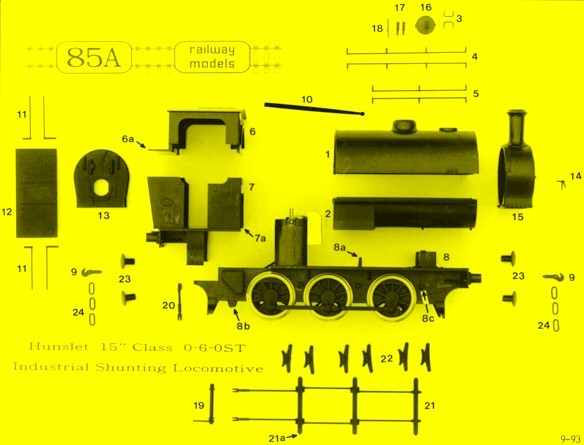
#
description
quantity
-------
----------------------------------------
------------------------
1
upper saddle tank
1
2
lower tank / boiler / firebox
1
3
tank filler grab rails
2
4
upper tank handrails
2
5
lower tank handrails
2
6
upper cab
1
7
lower cab / bunker
1
8
working chassis / frames unit
1
9
coupling hooks
2
10
reversing rod
1
11
cab doorway grab rails
2 pairs
12
bunker front
1
13
boiler backhead
1
14
smokebox door handles fitting
1
15
smokebox
1
16
tank filler cap
1
17
safety valves
2
18
whistle
1
19
brake cross-shaft
1
20
brake operating linkage
1
21
brake rigging moulding
1
22
brake hangers / blocks
3 pairs
23
working buffers
4
24
coupling links
6
blackened pin
1 ( for tank filler knob )
supply of plastic rod
1 ( for smokebox door hinge )
bag of washed coal for bunker
1
special grease
1
fine (1000 grit) abrasive paper
1
photograph of completed model
1
set of instructions
1
sturdy storage box
1
( i.e. the crumbly yellow flakes of padding material inside your parcel.
The material we are currently using looks very much like potato crisps! So
keep it away from young children and dispose of it carefully. When we next
re-order this, we will attempt to get it in a more sensible colour.)
![]() It is possible for this material
to mark the surface of plastic models and mouldings after prolonged contact.
Seal it inside a polythene bag if you want to use it as packing for your
model.
It is possible for this material
to mark the surface of plastic models and mouldings after prolonged contact.
Seal it inside a polythene bag if you want to use it as packing for your
model.
We are now on the Internet. You can email us at: martin@templot.com or
visit our web site at: www.85a.co.uk
![]() We hope to make this site a general
forum about our Hunslet model, with the latest hints and tips for construction,
modifications, additional detailing, prototype information, etc. If you have
something you would like to pass on to other modellers, please let us have
it (by post br email). We also hope to have a picture gallery of finished
Hunslets, so if you have a photograph of your model which you would like
to show to other modellers, please send it in - we will return it undamaged.
All contributions to the site will be duly credited, of course, unless you
say otherwise.
We hope to make this site a general
forum about our Hunslet model, with the latest hints and tips for construction,
modifications, additional detailing, prototype information, etc. If you have
something you would like to pass on to other modellers, please let us have
it (by post br email). We also hope to have a picture gallery of finished
Hunslets, so if you have a photograph of your model which you would like
to show to other modellers, please send it in - we will return it undamaged.
All contributions to the site will be duly credited, of course, unless you
say otherwise.
We shall be including as many links to other sites of 0 Gauge interest as
we can fit in - if you have your own site or know of a useful one, please
let us know.
This site is currently under construction, so if your first visit is a little disappointing, please try again soon.
![]() A note for experienced modellers
intending to modify the electrical connections:
A note for experienced modellers
intending to modify the electrical connections:
If additional wiring to the pick-up assembly is required, make any new connections to the unused forward-facing tags. Soldering to the rear-facing tags in situ can spoil the working of the pick-ups on the centre axle. If the existing wiring to the rear tags needs to be disconnected, this should be done by cutting the wires, not by unsoldering them.
This model is designed and intended for domestic and hobby use. If required for commercial display purposes please ask for our advice.
![]() If this model is run at full
speed for long periods (for example on a club test-track, or as part of a
window display), the motor will become noticeably warm. Although we have
not had any cases of motor problems due to overheating, if heavy use is
anticipated you may want to bear the following points in mind :
If this model is run at full
speed for long periods (for example on a club test-track, or as part of a
window display), the motor will become noticeably warm. Although we have
not had any cases of motor problems due to overheating, if heavy use is
anticipated you may want to bear the following points in mind :
Do not exceed our recommended maximum running weight of 12 oz. (340 gm), or run the model continuously around curves of less than 30 in. (750 mm) radius. Do not load the engine with a train so heavy that wheel-slipping occurs.
Attend to regular maintenance and wheel cleaning, and ensure that the gears and axle bushes are properly lubricated with the special grease supplied. Do not attempt to lubricate the motor - it is maintenance-free.
Many model controllers have a maximum output well in excess of the nominal 12 volt rating. For continuous running a regulated power supply is preferable.
Leave an adequate air-space around the motor when adding weights in the tank space, and avoid blocking completely the air-flow through the tank.
If modifying the cab-to-chassis fixing, or adding weight below the cab, avoid blocking the air-flow under the cab floor into the motor space.
The blind hole in the base of the chimney can be drilled through into the smokebox space to increase air-flow.
Painting the motor matt black will help to keep it cool.
![]() If this model is to be used only
for normal intermittent layout running and shunting purposes, air-flow and
motor cooling will not need to be considered.
If this model is to be used only
for normal intermittent layout running and shunting purposes, air-flow and
motor cooling will not need to be considered.
![]() In designing this model we opted
for a one-piece assembly to give the maximum strength to the finished structure.
This does not mean that the motor becomes inaccessible - see the notes about
motor replacement in section A.
In designing this model we opted
for a one-piece assembly to give the maximum strength to the finished structure.
This does not mean that the motor becomes inaccessible - see the notes about
motor replacement in section A.
But some modellers prefer to be able to dismantle the body of the model from
the chassis, and this is not difficult to arrange. The smokebox should be
fixed permanently to the chassis, to provide a clip-in front fixing for the
separate one-piece cab/tank assembly.
The cab/tank part is then fixed to the rear frames with a bolt through the
cab floor. A rectangular piece of thick plastic card (with a hole for the
bolt) will need to be fixed between the rear frames. If infrequent dismantling
is expected, a self-tapping screw directly into the plastic of the cab floor
will be adequate; a thick piece of plastic card cemented to the underside
of the cab floor will give more purchase for the screw.
Avoid over-tightening the fixing screw, which could distort the frames, causing
the rear axle to bind.
![]() It may be desired to leave the
upper cab detachable to allow access to the cab interior. Bear in mind that
this modification will reduce the rigidity of the finished body structure.
It will be necessary to cut away the front of the upper cab to clear the
top of the backhead when engaging the curved rib into the tank, and to chamfer
the ends of the rib. Alternatively, the backhead could be fixed only to the
upper cab so that both detach together.
It may be desired to leave the
upper cab detachable to allow access to the cab interior. Bear in mind that
this modification will reduce the rigidity of the finished body structure.
It will be necessary to cut away the front of the upper cab to clear the
top of the backhead when engaging the curved rib into the tank, and to chamfer
the ends of the rib. Alternatively, the backhead could be fixed only to the
upper cab so that both detach together.
![]() We do not recommend the fitting
of a flywheel to the upper motor shaft. Unless perfectly balanced, it is
likely to cause premature wear in the motor bearings. If a flywheel is fitted,
it will need to be angled to clear the interior of the saddle-tank. The flywheel
must not be larger in diameter than the motor if the body parts are not being
made detachable (see above), and removal of the motor through the frames
is to remain possible.
We do not recommend the fitting
of a flywheel to the upper motor shaft. Unless perfectly balanced, it is
likely to cause premature wear in the motor bearings. If a flywheel is fitted,
it will need to be angled to clear the interior of the saddle-tank. The flywheel
must not be larger in diameter than the motor if the body parts are not being
made detachable (see above), and removal of the motor through the frames
is to remain possible.
This pack contains metal handrails and knobs to replace the moulded parts # 3, 4, 5, 11.
The pre-drilled holes in the tank mouldings for parts # 4 and # 5 may need to be enlarged slightly to accommodate the metal handrail knobs. Sand over the holes to remove any raised burrs, so that the knobs can sit flush.
The longer length of handrail wire is first used as an assembly aid. Slide the knobs for one handrail along it and tape the ends to avoid losing them. Locate each one in position and tape over it with masking tape to hold it in place. Now apply rapid-set epoxy adhesive or "Milliput" inside the tank to retain the knobs. When set, withdraw the long wire and repeat for the remaining handrails.
Slide in the shorter pieces of wire, which have been cut to the exact lengths. Apply a little superglue on a needle to fix them in each knob.
Or, for a neater result, cut or file them a fraction shorter, so that they reach only to the centre of the end knobs. Fill the exposed hole in each end knob with a speck of "Milliput" or other filler. When set, sand the filler to match the round profile of the knob. No other wire fixing should be needed.
The longer length of wire can now be used to form the grab rails, parts # 3 and # 11. Cut and bend them to shape, using the moulded parts as a pattern. Fix them in place using rapid-set epoxy adhesive.