| Templot Companion | search | remove search highlighting | if the A-Z Index tab is missing click here |
real track
This page is a temporary re-hash from the old Templot companion to keep the information available. It will be re-written with expanded explanations for Templot2 soon.
quick page links:
types of switches types of V-crossings setting the stock rail types of switch blade planing
joggled stock rails split-deflection switches planing dimensions wing and check rail dimensions
There are 3 types of switch available in Templot. These diagrams illustrate the differences between them.To select the type of switch for your turnout, click the real > switch settings... or template > switch settings... menu items.
1. In a straight switch, the switch rail (point blade) is straight over its full length, shown in pink above. The turnout curve (shown in green above) commences at the heel of the switch, and is tangential to the straight switch blade. This type of switch is usually constructed as a loose-heel switch, meaning that the switch rails are free to pivot at the heel. The size of a straight switch is normally specified as the length of the switch rails, e.g. 9ft, 12ft, etc. In some designs (including those in Templot) this measurement is taken to a virtual heel position which is a little way short of the actual rail end.
2. In a semi-curved switch, the switch rail (point blade) is straight only over the length of the planing (tapered section) shown in pink above. For the remainder of its length to the heel, it is curved at the switch radius, shown in yellow above. The turnout curve (shown in green above) commences at the heel of the switch, and is tangential to the switch radius. Often the turnout curve radius is less than the switch radius. It is never greater than the switch radius. If the switch radius and turnout radius are equal, this size combination of switch and crossing is called a natural turnout. This type of switch is usually constructed as a flexible switch meaning that the switch rails are held rigidly at the heel and movement of the switch blades is achieved by flexing (bending) them.
The most commonly used semi-curved switches are the REA bullhead-rail switches used in the UK from about 1923 onwards. The size of these switches is specified as a code letter, A, B, C, etc., size A being the shortest.
3. In a curved switch, the switch rail (point blade) is curved at the switch radius over its full length from the tip to the heel, including the planing, shown in yellow above. The turnout curve (shown in green above) commences at the heel of the switch, and is tangential to the switch radius. Often the turnout curve radius is less than the switch radius. It is never greater than the switch radius. If the switch radius and turnout radius are equal, this size combination of switch and crossing is called a natural turnout. This type of switch can be constructed as a loose-heel switch or a flexible switch according to the design. Flexible curved switches were used by the GWR from about 1930 (in preference to the REA semi-curved switches used by most other UK railway companies).
There are 4 types of V-crossing available in Templot. These diagrams illustrate the differences between them. To select the type of V-crossing for your turnout, click the real > V-crossing options > V-crossing settings... or template > V-crossing settings... menu items.
1. In a regular V-crossing, the turnout curve (shown in green above) finishes a little way short of the fine-point (gauge-line intersection). The straight section from the end of the turnout curve to the fine-point is called the V-crossing entry straight.
Regular V-crossings are the default type in Templot and are typically used for running-line crossovers.
2. In a generic V-crossing, the turnout curve (shown in green above) finishes at the fine-point (gauge-line intersection), and there is no entry straight to the V-crossing.
Generic V-crossings are mainly used in Templot when matching an exact prototype turnout size in exact-gauge models such as P4, S7, etc.
3. In a curviform V-crossing, the turnout curve (shown in green above) runs through and beyond the fine-point (gauge-line intersection). This causes the turnout road to diverge more rapidly from the main road than is the case for regular and generic V-crossings of the same angle.
Curvifom V-crossings are often needed where there is contraflexure curving in the main road (unless it is part of a crossover), and also for double-junctions.
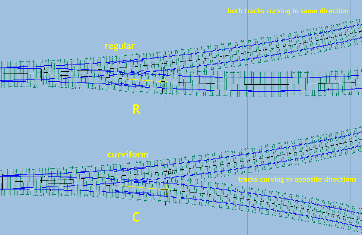
Changing from a regular V-crossing to a curviform V-crossing causes the curving in the part of the turnout marked in yellow above to change direction, so that it matches the direction of curving in the diverging branch track.
4. A parallel V-crossing is a special case of a regular V-crossing, in which the turnout road beyond the V-crossing curves back to run parallel with the main road. There is a short length of straight through the V-crossing itself, between the end of the turnout curve and the start of the return curve.
 In all of the above V-crossing diagrams, the rails shown in grey are straight if the main road through the turnout is straight. If the main road is curved, all of the rails shown in grey are curved to that same radius, including any V-crossing entry "straight".
Setting the Diverging Stock Rail :
The diagram below shows the position of the set (bend) in the diverging stock rail, which matches the planing angle on the switch blades and is needed to ensure a correct track gauge through the turnout road of the switch. Templot puts a mark across the diverging stock rail at the position of the set, as shown (for a left-hand switch).
The opposite straight (main-road) stock is plain rail, and has no set.
The set is slightly in advance of the tip of the opposite blade, as shown, and in order to ensure that the geometry works correctly the TP peg position (CTRL-2) is in advance of the blade tip by half this amount.
The diagram shows the set mark at the minimum amount of set advance. There is no harm in having a little more, and some prototype companies specified a dimension of 2"-4" for this to help protect the mating blade tip from wheel damage. However, an excessive set advance should be avoided as this can cause a knock to the wheels of trailing traffic. Often for facing traffic, and on all GWR switches, the set is replaced with a joggle (see below).
When building a model switch, it is convenient to approximately double the set advance shown, and to align the set to the leading edge of the S1 timber. In making the set (bend) in the stock rail, the angle can be checked by measuring the stock gauge dimension. For more information about the stock gauge, see split-deflection switches below.
These notes apply to UK-pattern bullhead track only.
1. Undercut Switch Blades with Plain Stock Rails :
These first diagrams below show the left-hand stock rail and switch blade for a left-hand undercut-pattern switch with a plain unjoggled stock rail. This is the type of blade planing most often modelled because it requires only a plain set in one stock rail only.
A set (bend) is put in the turnout-side (TS) stock rail at the toe of the switch (blade tip) to match the planing angle on the switch blade. The opposite main-side (MS) stock rail is plain rail.
The switch blade is planed (machined) to a sharp tip, and profiled down below the top of the stock rail to fit under the head of the stock rail (undercut). This is in order to have sufficient strength at the tip.
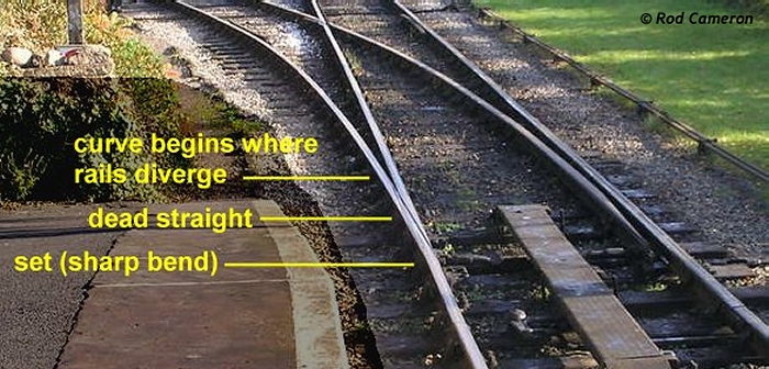
Such a blade acts only as a guide to the wheel flanges for the first part of its length and does not actually support the weight of wheels running onto it until they have reached some way along it. Undercut switches can often be identified in photographs because the shiny top of the open blade stops some way short of the tip.


Here are some photos of an undercut switch. You can see from the shiny marks on the top of the blade that it starts to take some part of the wheel load at about the position of the second stretcher bar. Up until that point it is simply guiding the wheel flange, and is dull on top:


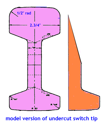
You can see that the tip is very thin, and if continued up to the top of the stock rail it would be a knife edge.
The way to model this is to simplify the planing like this:
The final shaping is then done with fine abrasive paper ("Wet-or-Dry" paper from car shops), with the blade clamped against the stock rail. For some notes about this, see:
http://85a.co.uk/forum/view_topic.php?id=2802&forum_id=6#p19571
Notice also a seldom-modelled but quite prominent feature, the steel sole plate on the toe timber. It is used to hold the stock rails to gauge, so that the stretcher drive and detection rods can be accurately set. Usually there are strips welded on the ends of the sole plate to bear against the chair bases (just visible under the muck on the lower photo), or the ends of the plate are turned up as a forging for the same purpose. In the photos there is an insulated joint in the sole plate because this track is track-circuited.
2. Straightcut Switch Blades with Joggled Stock Rails :
When a more robust switch is needed, both of the stock rails are joggled outwards by a small amount to create a housing for the switch blade tips and so protect them from wheel damage. This next diagram below shows this alternative straightcut-pattern switch with a joggled stock rail.

Instead of a plain set in the stock rail at B, it is joggled sideways between positions A and C, with the maximum deflection from its previous unjoggled alignment being at the blade tip position B. In bullhead track this creates 3 bends in the rail, at A, B and C. In bullhead track the joggled section is always created by bending the rail rather than by machining a notch in it.
The switch blade is planed to a blunt tip (straightcut), to a thickness corresponding to the amount of joggle, which has been exaggerated in this diagram for clarity. Apart from a rounded corner at the tip the blade is the full height of the stock rail and plays its part in supporting the wheels along its full length. A straightcut switch can often be identified in photographs by showing a shiny top on the open blade all the way to the tip.

In defining a joggled switch, two additional dimensions are needed. The joggle depth (sideways deflection) at B, and the joggle return length in front of the blade tip between positions A and B, in which the rail returns to its normal alignment. (The length between B and C always corresponds to the planing length for the switch blade). These dimensions need to be entered when creating a custom joggled switch in Templot.
Having entered joggle dimensions for your custom switch, you can choose whether to actually use the joggles for an individual template by means of the joggled stock rails option tickbox.

The full prototype planing design shown above is difficult to replicate in small-scale models. The diagram below shows how a model blade tip can be prepared to fit into the joggle and align the running edge with the unjoggled part of the rail:
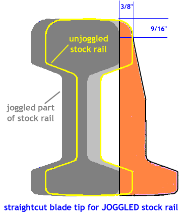
The extreme end of the blade is then rounded off to match the top corner radius on the stock rail.
The 9/16" dimension below the rail top is the gauging line, i.e. the position on the rail where the track gauge is measured.
(The diagram shows vertical rail. If you use inclined rail the dimensions remain the same.)
Here is a photo of a GWR joggled switch with straightcut planing. Notice the thicker more robust nature of the blade tip, and that it is full height and shiny all the way to the tip. Notice also that the depth of joggle in the stock rail is very small in relation to the rail width. It is not easy to create such a joggle in models.

Again the sole plate and the insulated joint in it are prominent.
Prototype notes:
REA and straight loose-heel switches can be either joggled or not - normally joggled switches are used only in facing positions on running lines. In trailing positions there is a danger of rough running when wheels hit the joggle return length on the open switch blade side, most severely when the main-road is curved. However, all GWR and BR(WR) switches are joggled .
For REA switches the joggle depth is 3/8" (0.375 inches) and the joggle return length is 6 inches. For older pattern straight loose-heel switches these dimensions vary, but are usually similar.
For GWR old-pattern switches the joggle depth is 3/8" (0.375 inches) and the joggle return length is 4 inches. The later GWR and BR(WR) curved flexible switches have a less severe joggle, the joggle depth is 1/4" (0.250 inches) and the joggle return length is 6 inches.
These joggle depths are barely perceptible in the smaller model scales. A 1/4" joggle is only 3 thou (0.003 inches) (0.08 mm) in 4mm/ft scale. Some modellers prefer a more pronounced joggle, and Templot provides for this with the generator > generator settings > rails > overscale joggles menu option, which creates a joggle depth of 3/4" (scale).
Visitors to the Severn Valley Railway steam heritage line in Kidderminster UK can very easily observe the difference between joggled and unjoggled switches. In platform 1 the engine release turnout at the buffer stops has an REA semi-curved flexible switch with undercut-pattern switch blades (no joggle). In platform 2 the engine release turnout has a GWR curved flexible switch with straightcut-pattern blades and joggled stock rails. The very much more robust nature of the blade tips in the latter case is very evident.
The following notes apply to UK terminology. In American terminology a "split" switch refers to a standard switch, so called to differentiate it from the much older type of "stub" switch.
Here is a sketch showing the difference between a standard switch and a "split" switch. The stock rails are shown in black, with the switch blades in blue. For simplicity the switch is shown undercut (unjoggled). I have greatly exaggerated the angles and rail widths to make things clearer:
In a standard switch (upper sketch) one stock rail is bent or "set" to match the planing angle on the blades, and the other stock rail is left as plain rail. Switches in running lines are always of this type, regardless of any curving of the rails, so that there is no deflection either way to vehicles running at full speed on the main road. Vehicles taking the turnout road, however, are abruptly deflected at the planing angle (in this case to the left when running left to right), and a speed restriction is therefore necessary over the turnout road.
In yards and sidings where speeds are low, if there is a contraflexure (Y-turnout or "negative curving radius" in Templot terminology) with the main road curving away from the turnout road (to the right in this case when viewed from the left of the diagram), it is often the practice to "split" the switch as shown in the lower sketch. This means putting a "set" in both stock rails so that the deflection is shared between the two roads.
If the deflection is shared equally between the two roads (50%-50% split), the switch is symmetrical or "unhanded", and the turnout is usually also symmetrical (perfect-Y) with an equal radius in each road. Where the turnout radii are unequal, it is usual to adjust the proportions of the split accordingly, and the sketch shows a 75%L-25%R split.
Note that the dimension labelled sg (sometimes called the stock-gauge) is the same in both diagrams, and is the distance between the stock rails at the limit of the blade planing. This dimension is equal to the track gauge plus the railtop width. When making the bends in the stock rails it is essential that this dimension is maintained - it is more important than getting the percentage deflections exactly right.
This process is called "setting the switch". Only the stock rails are affected. The blades, chairs, fittings, timber spacings and all other components are exactly as for a standard switch, and the planing angle on each blade does not change.
Sometimes a joggle (see above) is made in the stock rails to protect the blade tips, but the stock-gauge dimension remains unchanged. Templot can generate switch templates with or without joggled stock rails in versions 0.71 and later. Joggles are not used on trailing switches in running lines, except on the GWR.
The dimension labelled pl is the planing length on the switch blades. It is equal to the total deflection angle for the switch (as a unit angle) multiplied by the railtop width. It is also the same in both diagrams. When constructing model switches, it is important to check the dimension sg between the stock rails at distance pl from the blade tips before fitting the blades. sg can be checked by combining an oddment of rail with a track gauge, or be measured with calipers (gauge+rail-width).
Here is a handy chart of blade planing lengths and deflection angles for different switches:
switch size |
total deflection angle |
pl planing length |
pl 4mm scale |
pl 7mm scale |
A or 9ft |
1:24 |
66" |
22 mm |
38.5 mm |
B or 12ft |
1:32 |
88" |
29.3 mm |
51.3 mm |
C or 15ft |
1:40 |
110" |
36.7 mm |
64.2 mm |
D or 18ft |
1:48 |
132" |
44 mm |
77 mm |
E or 24ft |
1:64 |
176" |
58.7 mm |
102.7 mm |
F or 30ft |
1:80 |
220" |
73.3 mm |
128.3 mm |
These diagrams and dimensions apply to straight and REA semi-curved switches (straight planing). For switches with curved planing the pl dimensions differ but the principles are the same, and the sg dimension is the same.
See also A or B switch?
Wing and check rail dimensions :
For more information see: check and wing rails.
This diagram explains the wing rail and check rail (guard rail) terminology used in Templot. Everything is referenced from the centre of the "A" timber -- the one supporting the nose of the crossing vee:
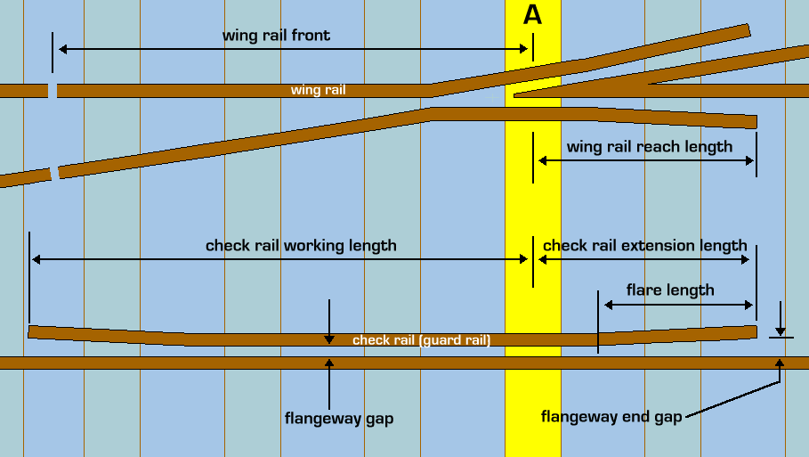
These dimensions can be customized from the real > customize V-crossing > wing and check rails ... menu item. The settings there are the defaults applied to all templates. To modify the individual check and wing rails on a specific template, click the real > adjust check rails... menu item. For more information see: check and wing rails.
The wing rails are the short lengths of running rail with bent extensions which lie alongside the nose of the crossing vee. The wing rail "reach" length is measured from the centre of the "A" timber (the timber bearing the nose of the vee) to the free end of the wing rail.
(To set the wing rail "front" length from the rail joint to the "A" timber, click the real > customize V-crossing > wing rail front ... menu item.)
The check rails (guard rails) are the short lengths of rail fixed alongside the opposite running rail to prevent the wheels from taking the wrong path at the nose of the crossing. For dimensioning purposes the overall length of a check rail is divided into two component lengths, named "working length" and "extension length".
The check rail "working" length is measured from the position where it crosses the centre-line of the "A" timber, to the near end of the check rail (the end which is nearer to the switch) (point blades).
The check rail "extension" length is the remaining length from the "A" timber to the far end of the check rail.
Templot uses 2 sizes of wing rail reach length, 3 sizes of check rail working length and 2 sizes of check rail extension length, according to the V-crossing angle. These sizes are preset in increasing lengths, but can be set to be all the same, or to any desired lengths.
Here is a summary of the way these sizes are used according to the current V-crossing angle:
V-crossing check rail check rail wing rail
angle: working length: extension length: reach length:
under 1:6 size 1 size 1 size 1
1:6 to 1:10 size 2 size 1 size 1
over 1:10 to 1:12 size 2 size 2 size 2
over 1:12 size 3 size 2 size 2
When customizing the dimensions, be sure that you are changing the settings for the appropriate size according to the current V-crossing angle. Otherwise your changes will have no effect.
In the majority of cases, the check rail extension length is the same dimension as the wing rail reach length, so that the far end of the check rail is aligned with the end of the wing rail, but this can be changed as necessary by entering the appropriate dimensions.
Be aware that because the check rails are linked to the "A" timber, the position of the check rails will change when changing the style of timbering (equalized, square-on, or angled-on). But their position is not affected by any timber shoving which is applied to the "A" timber.
link to this page: https://85a.uk/templot/companion/real_track.php